34,908 bytes. 358 x 504 pixels.
| astronautix.com | LK |
|
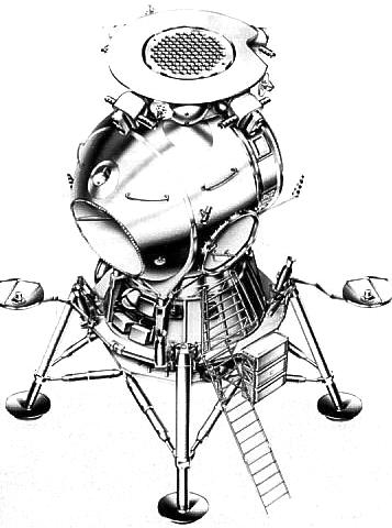
| LK Overhead - Overhead view of the LK lander, showing Kontakt docking system hexagonal grid docking structure. Exit hatch and ladder are to the right; scallop for main view port at front. Two high gain antennae at either side provided transmission of television from the lunar surface to earth. 34,908 bytes. 358 x 504 pixels. |
The LK ('Lunniy korabl' - lunar craft) was the Soviet lunar lander - the Russian counterpart of the American LM Lunar Module. The LK was to have landed a Soviet citizen on the moon before the Americans, winning the moon race. This was not to be, for reasons covered elsewhere (see Soviet Manned Lunar Projects). Because the translunar payload of the Russian N1 rocket was only 70% that of the American Saturn V, the LK differed in many ways from the LM. It had a different landing profile; it was only 1/3 the weight of the LM; it was limited to a crew of one; it had no docking tunnel (the cosmonaut had to space walk from the LK to the LOK lunar orbiter). Unlike the LM, the LK did not use a separate descent stage to go from lunar orbit to landing on the surface. A braking stage, the Block D, took the LK out of lunar orbit and slowed it to 100 m/s at an altitude of 4 km above the lunar surface. From there the LK used the engines of its Block E stage to soft land on the moon. The Block E also served as the ascent stage to return the LK to lunar orbit.
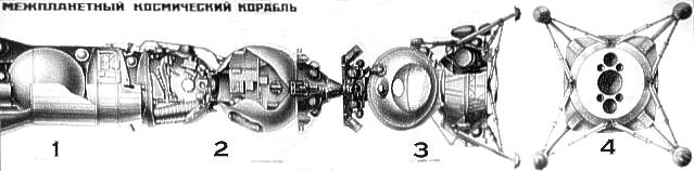
The LK consisted of four primary modules:
Consider now the LK in depth. This article is organised into the following main sections:
The N1-L3 Lunar Mission Profile
On 3 August 1964, Command number 655-268 issued by Central Committee of Communist Party gave Soviet Chief Designer Korolev the objective of putting one man on the moon and returning him safely to earth - ahead of the Americans.
Prior to this, Korolev had concentrated on the earth orbit rendezvous method. His September 1963 L3 design was a 200 tonne direct-lander requiring three launches of his giant N1 rocket and assembled in low earth orbit. This L3 spacecraft would make a precision 'blind' landing, homing in on a beacon aboard an L2 robotic lunar rover which had already been parked at a suitably flat touch-down point. The 138 tonne trans-lunar injection stage would propel the L3 spacecraft towards the moon. The 40 tonne lunar braking stage would ignite 200 to 300 km above the surface. After burnout, it would separate above the surface, allowing the 21 tonne lunar soft landing/ascent stage, with variable-thrust engines to make a soft landing on the surface. The landing leg structure and soft landing engines would be left behind on the moon. The ascent stage would propel the 5 tonne Soyuz L1 manned spacecraft back to earth. This capable but expensive spacecraft would have accommodated a crew of three for ten days of lunar surface exploration.
 | LK Landing Profile - Landing and abort profile of the LK lander. Credit: © Mark Wade. 14,000 bytes. 574 x 360 pixels. |
 | LK Lunar lander - LK lunar lander in assembly hall. Credit: RKK Energia. 26,236 bytes. 345 x 240 pixels. |
 | LK - Overall view of the LK preserved at the Orevo Museum of the Bauman Moscow State Technical University. Credit: © Mark Wade. 51,734 bytes. 396 x 655 pixels. |
 | LK egress tests - Numerous tests were conducted to determine the best hatch and ladder configuration for the cosmonaut in the bulky Kretchet spacesuit. It was found the standard Soyuz hatch had to be replaced by a customized oval hatch. Credit: RKK Energia. 18,580 bytes. 310 x 240 pixels. |
 | LK Interior - Rare view of suited cosmonaut in the interior of the LK Interior during landing training. The cosmonaut had a viewing angle to the surface through the main window of 7 degrees from the vertical. A collimator indicated the predicted LK landing point. Credit: RKK Energia. 17,413 bytes. 312 x 240 pixels. |
 | T2K in Shop 39,236 bytes. 403 x 317 pixels. |
Development of the LK
 | LK interior left - View of the LK interior to the left of the cosmonaut, showing the cabin depressurization control panel, the radio control panel, cabin depressuriztion valve, and the edge of the exit hatch to the left. Credit: © Mark Wade. 62,809 bytes. 392 x 575 pixels. |
The advance design project for the N1-L3 was completed on 30 December 1964. The decree for production of 16 shipsets of spacecraft and boosters was issued on 26 January 1965. The N1-L3 was to manufactured to the following schedule: 4 in 1966; 6 in 1967; and 6 in 1968. The plan was for the first launch of the N1 to be in the first quarter of 1966, with the first lunar landings in 1967 to 1968, ahead of the American goal of 1969.
 | LK First Mockup - Early egress tests in the very first LK mockup. This mockup shows the earlier configuration of the lunar cabin, Block E landing / ascent stage, and LPU landing gear. 32,602 bytes. 360 x 306 pixels. |
 | T2K Shroud on Pad 14,140 bytes. 193 x 284 pixels. |
 | LK interior right - View of LK interior to the right of the cosmonaut. The large viewport provides good visibility for the piloted descent to the lunar surface. The smaller viewport is for use in rendezvous and docking with the LOK lunar orbiter. Pre-programmed sequences were called up on the blue sequencer master panel, with guarded switches for initiating major engine burns and explosive events. Environmental control system box at left provides connections to the cosmonaut's Krechet space suit. Credit: © Mark Wade. 63,179 bytes. 580 x 398 pixels. |
The landing radar system was designated Planeta. Planeta consisted of four antennae, with their beams arranged in an asymmetric pyramid. Three determined the velocity vector using Doppler, while the fourth beam, in the central position, determined altitude above the surface. The system was simple and reliable. It was later proven on the Luna Ye-8 automated lunar sample return probes.
 | LK Evolution - Steps in evolution of the LK lunar lander. Top row, from right to left: development of the Lunar Cabin progressed from a simple sphere housing a seated cosmonaut with separate twin equipment sections, to a single equpment section, then finally to the complex shape with separate equipment module required to provide good visibility for landing and docking. Middle row: Development of the Block E landing/ascent rocket stage was dictated by the requirements of minimum weight, symmetric depletion of the propellant tanks, and an aerodynamic shape to deflect exhaust at landing away from the engine bell. Bottom row: alternate LPU landing gear approaches considered. From left: toroidal landing ring, housing LPU equipment; wild landing bag/water stabilised approach; variants on conventional gear. 37,434 bytes. 798 x 395 pixels. |
Ignition of the Block E stage was commanded automatically by the Planeta system when the LK was 3 km from the touchdown point. After eliminating the vertical velocity, the final landing manoeuvre was commanded by the cosmonaut. Landing was made in the deep throttle range of the Block E. Engine shutoff was commanded automatically by the Planeta system.
 | LK LPU-Draft & Final - Detailed design of the LPU landing gear. At the top: design at the stage of LK draft project. At the bottom: the final production design. 29,224 bytes. 364 x 360 pixels. |
In 1968 the L3 scheme was overhauled. The original scheme had assumed a landing on the lunar equator. This meant that the LOK orbiter would pass over the landing site once per orbit, every hour. For the ascent of the LK to the rendezvous orbit in this case, a simple gyroscopic platform could accomplish the launch, as was used on the V-2 and R-7 missiles.
 | LK interior back - View of the LK behind the cosmonaut. Environmental control, cooling, and electrical connections snake around the cabin. The round connection port to the left provides connection of interior service lines to the exterior cable/line bundle. The large round aft cover goes to the instrument section mounted to the rear of the spherical LK cabin. Credit: © Mark Wade. 65,095 bytes. 577 x 400 pixels. |
 | LK Landing Tests - A subscale model of the LK's LPU landing gear were used in tests to verify the use of 'nesting rockets' - downward-firing motors that would plant the lander firmly on the surface at slopes of up to thirty degrees. Credit: RKK Energia. 16,798 bytes. 308 x 238 pixels. |
 | LK Crew Station - A view of the actual fully-equipped LK crew station. Significant equipment is present that is not in the mock-ups that can be viewed today. Note the collimator/aiming reticule over the landing viewport; the cabin crowded with pilot restraints, pipes, and equipment racks. It is clear why accomodation of more than one cosmonaut in this space was not feasible. 43,605 bytes. 413 x 311 pixels. |
 | T2K Cabin 34,280 bytes. 407 x 292 pixels. |
The LPU - lunniy posadocnie ustroistviy - was the landing leg assembly of the LK. It would remain behind on the surface, acting as a launch pad for the Block E rocket stage. .Therefore the LPU not only to had to absorb the shock of landing, but provide a level base for the ascent stage as well. All systems not necessary for ascent were attached to it. A A Sarkisyan was in charge of LPU design.
The overall LK mass problem meant that there was only sufficient reserve propellant to move no more than 100 m from the original landing point selected by the automated system. Studies of Ranger photographs of the lunar surface indicated that the 100 m requirement meant that it was most likely the LK would land in a crater of 7 m diameter. This translated into the specification that the LPU be able to handle slopes of 30 degrees with the LK centre of gravity being 2.5 m above the surface. The requirement for high confidence unmanned landings also played a role in the stiff requirement.
 | LK LPU - View of the LK Block E to the right of the cosmonaut ladder. The blue antenna is part of the landing radar system. The instruments for this were mounted in a globular housing (missing on this mockup) mounted on the aluminum struts. These would have been left behind with the landing platform when the LK ascended to lunar orbit. Tanks for oxygen and water are arranged around the LPU in a manner to ensure the center of gravity of the LK remains on the thrust axis. That's the fin of a Scud missile in the foreground. Credit: © Mark Wade. 65,211 bytes. 572 x 400 pixels. |
 | LK Egress Tests - Another view of LK egress tests. This view makes clear the large size of the backpack of the Kretchet suit and the tight squeeze getting into and out of the LK lander. Credit: Filin. 36,740 bytes. 249 x 360 pixels. |
 | LK panels - The cosmonauts' view of the LK viewports and control panels. On the left, environmental control and cabin depressurization controls (ligh blue panel); radio controls (dark green panel); large porthole looking down at lunar surface during landing. The small porthole looked upward for docking. The optical devices that were associated with these portholes are not present in this mock-up. To the right, sequencer panel for calling up sequences for maneuvers, landing, rendezvous, and docking. Guarded switches initiated major events. One of two hand controllers is visible below the green radio panel. Credit: © Mark Wade. 75,401 bytes. 788 x 354 pixels. |
Mounted on the LPU were those systems not required after the landing on the moon: the landing altimeter, parabolic antennae, chemical batteries, and three water tanks for the evaporative cooling system (a fourth was added late in development to trim the centre of gravity).
 | LK IOS View - View of the LK Lunar Cabin and the Integrated Orientation System at the top of the cabin. Note the angled position of the main thrusters, the omnidirectional 'carrot' anntenna at the lower right, and the hexagonal housing of the solar/stellar sensors at the upper right. 35,291 bytes. 410 x 252 pixels. |
A cabin environment using pure oxygen at 0.40 atmospheres was considered, but the need to develop special armatures, fire-proof materials, and the safety of the cosmonaut resulted in this being rejected. So the cabin environment selected was air at 0.74 atmospheres. This meant the cabin pressure vessel had to be twice as heavy, but this was considered worth it from a crew safety point of view.
Soviet experience in manual control of spacecraft was limited at the time of LK development. The development team had to return to first principles in determining the control layout and the position of the cosmonaut. The challenging requirements included the need to operate the controls in a pressurised space suit in the event of cabin depressurisation. Therefore foot pedals couldn't be used as in a fixed wing aircraft or helicopter. The design team consulted with helicopter and VTOL specialists at aviation design bureaux to solve these problems.
 | LK at Korolev - Large size photo of the production LK. Note the Vzor optical device fixed to the upward-looking porthole, which allowed the cosmonaut to determine and command attitude, range, and range rate information for docking with the LOK lunar orbiter. 130,800 bytes. 544 x 784 pixels. |
The Kretchet spacesuit developed, the ancestor of those still used on Mir today, could be entered through a hatch in the back. There was an elaborate system of braces and tie-down strips to fix the cosmonaut in a standing position during spacecraft manoeuvres. This was because it was necessary to keep the centre of mass of the cosmonaut on the thrust axis of the engine.
 | Krechet Spacesuit - Krechet lunar space suit as displayed at NPO Zvezda. As in the Orlan suit still used on Mir, the cosmonaut entered the suit by swinging open a hatch at the rear. The backpack containing the life support system was housed in the backpack which made up the hatch door. As in Apollo, the gold-coated outer visor of the helment reflected ultra-violet radiation. The integrated Kretchet design meant that no external hoses were required as in the American Apollo suit. Credit: Andy Salmon. 18,771 bytes. 196 x 445 pixels. |
Due to weight considerations, no automatic docking system could be considered, as was used on the Soyuz spacecraft. The system objectives were minimum weight, manual operation, and tolerance to low accuracy docking. Since the cosmonaut would spacewalk from the LOK to the LK and back, no hard dock system, with system connections and a hermetic seal between the spacecraft, was required. The Kontakt system that was developed used a snare-like probe on the active LOK spacecraft. The LK was the passive vehicle, and was equipped with a 1.8 metre diameter, lightweight hexagonal alloy grid. Each of the 108 hexagons was a potential receptacle for the LOK's docking probe.
 | Krechet Spacesuit - Front view of the Krechet lunar space suit Credit: Andy Salmon. 23,974 bytes. 206 x 478 pixels. |
 | LOK-LK Drawing - Unusual diagram of LOK and LK lunar craft in docked configuration, with bottom view of LK. Korolev School. Credit: Jakob Terweij. 22,627 bytes. 639 x 158 pixels. |
Originally development of the Block E landing/ascent stage was considered the pacing item in LK development. Drawings for the Block E were already issued in parallel with the draft project. The original specification of 510 kg empty mass for the stage could not be met. There were constant mass allocation fights between the rocket block design team and the cabin design team.
The LK variable-thrust, restartable engines represented a huge engineering development task. Unusually, Yangel decided to develop the system within his own OKB rather than entrust it to one of the traditional engine design bureau. New materials and new mechanical solutions were required to obtain a reliable, safe, redundant, durable engine that could be used over a wide variation of payload mass. In charge of Block E engine development was Ivan Ivanovich Ivanov, known to all as I-Cubed.
 | LK at Korolev - LK exhibited at Korolev School. Note the optical device on the upper porthole, part of the semi-automatic optical docking system. This is not seen on other LK's exhibited. Credit: Jakob Terweij. 38,493 bytes. 298 x 480 pixels. |
 | LK Base / Korolev - Closeup view of the engines of the LK exhibited at Korolev School. Credit: Jakob Terweij. 64,036 bytes. 578 x 392 pixels. |
 | LK Interior-Korolev - Interior of the LK exhibited at Korolev school. Note the optical device on the upper porthole, part of the semi-automatic optical docking system. This is not seen on other LK's exhibited. Otherwise this LK seems to be equipped with earth-orbit systems of the T2K, rather than the lunar landing system panels. Credit: Jakob Terweij. 56,939 bytes. 578 x 392 pixels. |
The Integrated Orientation System was mounted above the Lunar Cabin. Yangel had no experience in microthrusters, so development of this system was subcontracted to Isayev. The same N2O4/UDMH propellant combination was used as in the Block E. The forward mounting of the package meant that the installation was 'unclean' - i.e. it introduced not only motion around the centre of gravity of the LK, but translation motions as well. The thrusters were arranged in two independent, redundant systems. In each system 2 x 40 kgf thrusters provided pitch; 2 x 40 kgf yaw; and 4 x 10 kgf for roll. Propellant totalling 100 kg was stored in two tanks. The problem arose how to preserve the centre of mass of the module on the main thrust line of the LK. The solution was to enclose the oxidiser tank within the propellant tank in a double-walled barrel construction.
 | LK Interior-Korolev - Interior of the an unknown LK also exhibited at Korolev school. This has partially-installed lunar landing instruments. Credit: Jakob Terweij. 63,175 bytes. 576 x 390 pixels. |
 | LK Test Article - Subscale dynamic test article of a late configuration of the LK, as preserved in the TsniiMash museum. Thi shows well the complex shape of the Lunar Cabin and the final LPU configuration. Credit: © Mark Wade. 45,855 bytes. 359 x 461 pixels. |
When the final drawings were reviewed, there was a major fight between the Yangel and Korolev bureaux over a 12 kg 'deficit' in the computed total mass out of the five tonne total. Korolev's bureau used this to put the entire design into question. After frantic study, the difference was traced to calculation involving the inert gas used for propellant tank membrane pressurisation.
Vibration and environmental tests were conducted on equipment at selected stages of fabrication and assembly. Flight tests were conducted of some components.
 | LK interior hatch - View of the LK exit hatch. This is a simplified representation of the real hatch. Note the spherical bulkhead that forms the floor of the LK. Credit: © Mark Wade. 47,229 bytes. 573 x 400 pixels. |
Mock-ups and test stands used in LK development included:
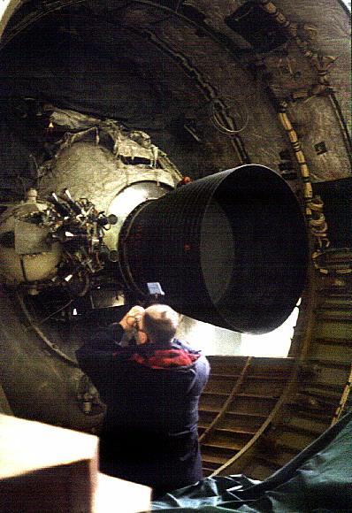
 | LK Block E - The Block E landing/ascent stage of the LK, viewed separately from the LPU landing gear. Note the clean aerodynamic shape and the engine guards, necessary to divert exhaust gases and debris away from the engine nozzle during landing. 39,939 bytes. 411 x 320 pixels. |
The T1K and T2K versions of the LOK and LK, respectively, were designed for independent earth orbital flight tests of the spacecraft. The T1K was to be launched by Proton and the T2K (also designated LK6/T2K ) by the Soyuz launch vehicle. This special 11A511L version of the Soyuz booster was equipped with a strengthened upper stage and bulbous fairing to accommodate the LK. An entire separate development team under Yu M Labutin was required to develop the special systems necessary for unmanned earth orbit test operations. 20 such systems were used on the T2K, including modifications of those developed for the Soyuz spacecraft. The Labutin team also had to decide what systems could logically be tested in earth orbit and which could not.
 | LK landing leg - View of the LK leg to the left rear of the cosmonaut. Note the solid fuel nesting rocket mounted at an angle to the gear strut. Credit: © Mark Wade. 58,010 bytes. 579 x 397 pixels. |
Flight 1 - Follow the standard engine profile Flight 2 - Induce or simulate various abort profiles Flight 3 - Reserve in case of failures on Flights 1 and 2
The flight programs were carefully constructed to allow time after each manoeuvre before the next one would be conducted. This allowed careful measurement of the resulting orbit after each manoeuvre in order to verify telemetered performance data, as well as time for playback of all telemetry, radio, and television of the events. It was difficult to arrange the schedule within the available LK battery amp-hours.
 | LK base - View of the base of the LK, below the ladder coming from the hatch. Credit: © Mark Wade. 58,478 bytes. 577 x 395 pixels. |
The T2K crews worked day and night preparing the spacecraft, and finally the first T2K was shipped to Baikonur for launch. Each T2K was tested before flight in a vacuum insolation chamber. During vacuum chamber tests at Baikonur, one of the equipment sections decompressed. It was found to have had ten microscopic holes punched into it during transport. These were repaired. Finally fuelled and cleared for launch, the first T2K was launched on a sunny morning in November 1970. The three tests of the T2K went of without a hitch:
 | LK Kontakt Dock Grid - The LK was normally the passive vehicle in docking with the LOK. Atop the LK was this grid of 108 hexagonal holes, each a potential docking port for the snare docking probe of the LOK. This system allowed docking to take place without precision allignment of the two vehicles. 23,856 bytes. 339 x 244 pixels. |
 | LK aft view - View of the aft of the LK behind the cosmonaut. The dish antenna is for beaming of television of the landing back to earth. The conical antenna is for omnidirectional radio communications. A water tank of the cooling system is flanked by the two gear with their nesting rockets. Credit: © Mark Wade. 70,654 bytes. 373 x 579 pixels. |
A two-crew version of the LK was studied for support of the Zvezda DLB lunar base planned after the initial landings. Space was so limited that special recesses would have to made in the cabin wall to accommodate the helmets of the two suited cosmonauts. However this was a moot point, since the increased payload required major modifications of the engines and propellant tanks, which were specifically designed for the single-crew, 5,500 kg LK. In the end it was decided that this was not practical. Larger lunar landers were instead designed by Korolev's bureau using Soyuz return capsules and descent stages copied from the American lunar module layout.
 | LK Egress Tests - Another view of LK egress tests, showing the challenge of squeezing through the LK hatch in the Kretchet suit. 17,627 bytes. 191 x 269 pixels. |
LK landers are preserved at the MAI museum in Moscow (this is a flight model that was displayed at Eurodisneyland in 1997), the MAI museum at Orevo (an engineering article), St Petersburg, the Energia plant at Korolev, north of Moscow, and at KB Yuzhnoye in the Ukraine.
Description of the LK
At the end of development the LK as designed had a mass of 5,560 kg, with the Block E stage weighing 2,950 kg. Takeoff mass from the lunar surface was 3,800 kg. The total height was 5.2 m. As with most aerospacecraft, the LK must be looked at from both a systems and a module viewpoint.
 | LK plumbing - Closeup of plumbing at the base of the LPU. This water tank was part of the LK cooling system. The markings indicate a capacity of 25.3 l. Credit: © Mark Wade. 53,833 bytes. 569 x 398 pixels. |
LPU
The LPU - lunniy posadocnie ustroistviy - was the landing leg assembly of the LK. The LPU was able to handle slopes of 30 degrees with the LK centre of gravity being 2.5 m above the surface. Solid propellant 'nesting' engines fired downward at the instant of touchdown to remove all tipping moments from the spacecraft. Mounted on the LPU were those systems not required after the landing on the moon: the landing altimeter, parabolic antennae, chemical batteries, and three water tanks for the evaporative cooling system (a fourth was added late in development to trim the centre of gravity). A video camera was externally mounted to give the ground a view of surface operations. It may be calculated from data given that the LPU, with its associated equipment, had a total mass of about 1,440 kg (5,560 kg LK mass - 280 kg descent propellant - 40 kg orientation system propellant used during descent - 3800 kg given as LK mass at start of ascent).
 | LK LPU detail - Closeup of the LK LPU section to the right of the cosmonaut. The red boxes are mockups of electronic black boxes. The oxygen tank and solid rocket nesting motors are clearly seen. Credit: © Mark Wade. 42,942 bytes. 571 x 397 pixels. |
The streamlined shape of the Block E allowed engine exhaust gases reflected from the lunar surface to flow up and away from the LK during landing. The Block E engines were equipped with clamshell doors, which closed at engine shut-off and prevented damage from lunar soil while the LK was on the lunar surface.
Total Block E mass has been given as 2,950 kg. It is stated that the original specification of 510 kg empty mass for the stage could not be met; assuming a 10% weight growth during development, the empty mass was probably around 550 kg. This would give a propellant load of 2,400 kg (volumetric capacity of the 2 x 1.2 cubic metre tanks was 2,600 kg). Propellant consumption in the landing manoeuvre was 280 kg, leaving about 2,100 kg for the ascent into orbit. The engines were rated to burn up to 2,900 kg of propellant (evidently a 10% margin over the tank capacity).
 | LK Block E detail - Closeup of the LK LPU section to the right of the cosmonaut. The red boxes are mockups of electrical / electronic black boxes and batteries. Credit: © Mark Wade. 51,619 bytes. 397 x 579 pixels. |
The engines were designed for maximum reliability, which meant minimum number of parts while achieving maximum redundancy. In addition, the primary engine had to be throttleable - the optimum thrust for the ascent phase was 2000 kgf, while hover during landing required variable thrust around 850 kgf. The main engine therefore had two main operating regimes: maximum thrust (OR) and deep throttle (RGD). The backup engines had only one thrust level, that required for ascent. The pump-fed engines were open cycle, and so were equipped with symmetric turbine exhausts.
 | LK Block E - Closeup of the side of the LK LPU section behind the cosmonaut. The large antenna would have deployed pointing upward to relay television pictures of the landing and moonwalk back to earth. Credit: © Mark Wade. 62,627 bytes. 582 x 400 pixels. |
Engine                      RD-858                   RD-859
No of chambers:                1                      2
Operating regime    nominal         throttled
Thrust in vacuum    2050 kg         858 kg           2045 kg
                    20104 N         8414 N           20055 N
spec. vac. impulse  315 s           285 s            312 s
                    3089 Ns/kg      2795 Ns/kg       3060 Ns/kg
Mixture ratio O/F   2.03            1.6              2.0
Thrust variation    +/- 9.8 %       +/- 35 %         +/- 9.8 %
Mixture ratio deviation        3 %                   3 %
Chamber pressure    80 kg/cm^2      33.8 kg/cm^2     80 kg/cm^2
                    78.5 bar        33.15 bar        78.5 bar
Operation time      50 + 350 s      100 s            400 s
Propellants               N2O4 / UDMH                N2O4 / UDMH
Engine mass                  53 kg                   57 kg
Propulsion system height                  1090 mm
Propulsion system width                   1102 mm
 | LK landing pad - Closeup of a landing pad, showing the construction of the strut and the fillets machines into the pad. Credit: © Mark Wade. 51,065 bytes. 398 x 574 pixels. |
The combined mass of the Lunar Cabin and Integrated Orientation System mounted above it may be calculated to be 1,130 kg at lift-off from the lunar surface, or about 1,200 kg with a fully-fuelled orientation system (3,800 kg LK mass at ascent - 2,670 kg Block E mass at lift-off). The cabin environment selected was air at 0.74 atmospheres. The cabin pressurisation / depressurisation system could not only be operated by the cosmonaut, but by ground control if necessary. A special oval hatch allowed exit of the cosmonaut in his Kretchet spacesuit.
 | Early Egress Test - Closeup of the earliest version of the Kretchet suit and LK mock-up during egress tests. 17,017 bytes. 192 x 280 pixels. |
An additional requirement was capability for completely automated landing and docking operations. This was required for both unmanned spacecraft tests and in emergencies involving a disabled cosmonaut or rescue of a cosmonaut stranded on the surface. This was handled by use of television cameras mounted above the head of the cosmonaut. This allowed ground control to guide the LK away from any ground obstructions by remote control.
 | LK ladder - Closeup of the ladder leading to the LK hatch. Credit: © Mark Wade. 48,828 bytes. 573 x 398 pixels. |
 | LK entrance hatch - The entrance hatch to the LK lunar lander. On the right is the large instrument section, with connector plates for interior/exterior connection of electrical, electric, and piping services. Credit: © Mark Wade. 56,456 bytes. 580 x 398 pixels. |
The external body of the cabin was used for mounting low-gain antennae, oxygen tanks, the thermo-regulation system, and other equipment.
The LK cabin was equipped with a 'ski-ramp' shaped brace that carried loads of the L3 stack (LOK at top, LK, then Block D) during launch and manoeuvres of the L3 complex prior to separation of the LK/Block D for the descent to the lunar surface.
 | LK IOS Closeup - Closeup view of the Integrated Orientation System block above the exit hatch, topped by the disk-shaped hexagonal mesh platform that the LOK would use to grapple the LK. The top of the instrument section, with the connection plate, is visible on the right. Credit: © Mark Wade. 41,464 bytes. 579 x 399 pixels. |
 | LK ladder base - Detail of the base of the ladder, showing the battery racks below the ladder. Note the shape of the foot pad. Credit: © Mark Wade. 50,394 bytes. 527 x 369 pixels. |
Integrated Orientation System
The Integrated Orientation System module was mounted on top of the Lunar Cabin. The thrusters were arranged in two independent, redundant systems. 2 x 40 kgf thrusters provided pitch; 2 x 40 kgf yaw; and 4 x 10 kgf for roll. Propellant totalling 100 kg was stored in two tanks, oxidiser tank within the propellant tank in a double walled barrel construction.
 | LK cabin - View of the LK cabin with a crude mockup of the Integrated Orientation System block atop it. The disc antennae around the top of the block are of unknown purpose; possibly part of a radio-locator system to assist in finding the LOK during rendezvous operations. Credit: © Mark Wade. 48,135 bytes. 578 x 397 pixels. |
Mounted on top of the Integrated Orientation System were the radiators of the thermo-regulation system and the hexagonal docking grid of the Kontakt system.
LK Systems
In terms of engineering management and development, the LK was divided into the following systems:
 | LK landing leg - View of the landing leg to the cosmonaut's front left. Note the solid rocket motors mounted above each leg that fired DOWN to settle the LK securely on the surface once the lander was near the surface. These greatly improved the chances of a safe landing. The system could handle landing on a 20% slope or with one leg on a moon rock. The descent ladder is seen coming from the hatch. The box at the base of the latter houses batteries for electric power. Credit: © Mark Wade. 68,926 bytes. 579 x 398 pixels. |
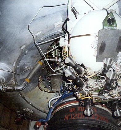
 | LK Main Engine - The LK engine cluster at the base of the lander. The single chamber RD-858 of the 2,050 kgf main engine is at the center. It is flanked by the two nozzles of the RD-859 2,045 kgf backup engine. The smaller nozzles are exhaust nozzles for the turbines of the pump-fed engines. At landing or takeoff, both the primary and backup engines would ignite. Only if both engines were operating, would one shut down. The thick clamshell doors closed over the engines after landing to insulate them and prevent injestion of lunar soil. Credit: © Mark Wade. 55,317 bytes. 577 x 398 pixels. |
 | LK landing leg - View of the landing leg to the cosmonaut's front left. Note the solid rocket motors mounted above each leg that fired DOWN to settle the LK securely on the surface once the lander was near the surface. Yangel OKB tests proved such rockets greatly improved the chances of the rocket not toppling if landing on a 30 degree slope or with one leg on a moon rock. The descent ladder is seen to the right of the picture. Credit: © Mark Wade. 44,828 bytes. 481 x 400 pixels. |
 | LK with Block D - LK with Block D Lunar Crasher stage. This is the configuration that would have braked until just above the surface, when the LK would have jettisoned the Block D, extended its legs, and maneuvered to a soft landing on the surface. Credit: © Mark Wade. 9,233 bytes. 236 x 619 pixels. |
 | Block D / 11D68 - Aft view of the Block D lunar crasher stage and its 11D68 engine. The Block D would have taken the LK lunar lander to near the surface of the moon. This stage remains in use today atop the Proton rocket. Credit: © Mark Wade. 52,122 bytes. 398 x 580 pixels. |
 | Engine 11D68 detail - Closeup view of the 11D68 Block D lunar crasher stage showing detiail of the BOZ orientation/ullage thrusters that control the stage during coast, restart, and maneuver. Credit: © Mark Wade. 43,376 bytes. 393 x 424 pixels. |
Craft.Crew Size: 1. Design Life: 3 days. Orbital Storage: 30.00 days. Total Length: 5.2 m. Maximum Diameter: 4.5 m. Total Habitable Volume: 5.00 m3. Total Mass: 5,560 kg. Total Propellants: 2,400 kg. Total RCS Impulse: 25,000.00 kgf-sec. Primary Engine Thrust: 2,050 kgf. Main Engine Propellants: N2O4/UDMH. Main Engine Isp: 315 sec. Total spacecraft delta v: 2,700 m/s. Electric system: 0.50 total average kW. Electric System: 30.00 total kWh. Electrical System: Batteries.
 | Apollo vs N1-L3 - Apollo CSM / LM vs L3 Lunar Complex Credit: © Mark Wade. 11,521 bytes. 621 x 332 pixels. |
Central Committee of the Communist Party and Council of Soviet Ministers Decree 655-268 'On Work on the Exploration of the Moon and Mastery of Space--piloted LK-1 circumlunar and L3 lunar landing projects and the Ye-6M lunar lander' was issued.
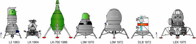 | Soviet Lunar Landers - Comparison of Soviet lunar lander designs. Only the LK reached the hardware stage. 23,098 bytes. 755 x 172 pixels. |
 | LK - Detail forward view drawing of the LK lunar lander. Credit: © Mark Wade. 8,592 bytes. 421 x 464 pixels. |
Interdepartmental Scientific-Technical Council on Space Research (MNTS-KI) Decree 'On approval of the L3 draft project' was issued. The decree followed a review by a Keldysh-led Academy of Sciences state commission the previous December. The decree moved the first flight of the N1 to the end of 1966.
 | LK Two View - Two view layout drawing of LK lunar lander. Credit: © Mark Wade. 8,008 bytes. 574 x 350 pixels. |
Central Committee of the Communist Party and Council of Soviet Ministers Decree 'On approval of the N1-L3 mission profile' was issued.
Academy of Sciences Decree 'On course of work on the N1-L3' was issued.
 | LK Lunar Lander - LK lunar lander. 19,698 bytes. 306 x 338 pixels. |
Military-Industrial Commission (VPK) Decree 'On creation of a commission to compare the UR-700-LK-700 and the N1-L3' was issued.
Decree 'On lag of work on the N1-L3 and UR-500K-L1 programs' was issued.
 | LK drawing at Kaluga - Cutaway drawingof LK lunar lander, showing position of cosmonaut in cabin. Credit: e. 40,125 bytes. 395 x 378 pixels. |
Decree 'On revision of the timetable for the N1-L3' was issued.
20 cosmonauts begin training for lunar landing. Decision after a year of acrimonious argument between Korolev OKB and military. Final slate: Air Force: Bykovsky, Filipchenko, Gorbatko, Khrunov, Kuklin, Leonov, Nikolayev, Shonin, Voloshin, Volonov. OKB: Feoktistov, Grechko, Kubasov, Makarov, Nikitski, Rukavishnikov, Sevastyanov, Volkov, Yazdovski, Yeliseyev.
 | LM vs LK - US Lunar Module compared to Soviet LK lunar lander Credit: © Mark Wade. 8,634 bytes. 663 x 315 pixels. |
Decree 'On approval of the training program for lunar cosmonauts' was issued. This incuded the final moon landing plan.
Original planned date for first test of LK in earth orbit.
LK moon lander test using the T2K version. First use of the Soyuz 11A511L booster modified especially for this purpose. The spacecraft made a series of engine burns, simulating the lunar landing profile. After 3.5 days in orbit, the first burn was made in imitation of a descent to the lunar surface after separation of the Block D lunar crasher stage. The orbit changed from 192 km X 233 km to 196 km X 1206 km orbit; delta V: 263 m/s. After 4 days in orbit, a large manoeuvre was made simulating the ascent from the lunar surface. The orbit was changed from 188 km X 1198 km to 177 km X 14,041 km; delta V: 1518 m/s. These main manoeuvres were followed by a series of small adjustments simulating rendezvous and docking with the LOK. The LK tested out without major problems and decayed from orbit on September 21, 1983.
Second space test of the LK moon lander test using the T2K version. Followed the same programme as Cosmos 379.
Maneuver Summary:
189km X 252km orbit to 186km X 1189km orbit. Delta V: 251 m/s
186km X 1189km orbit to 200km X 10905km orbit. Delta V: 1320 m/s
Total Delta V: 2832 m/s.
Officially: Investigation of the upper atmosphere and outer space.
Final LK moon lander test using the T2K version.
Maneuver Summary:
188km X 267km orbit to 190km X 1261km orbit. Delta V: 266 m/s
188km X 1262km orbit to 180km X 11384km orbit. Delta V: 1333 m/s
Total Delta V: 1599 m/s. Ten years later the spacecraft was due to re-enter over Australia soon after the Skylab scare. The Soviet Union told the people of Australia not to worry, it was only an experimental lunar cabin - the first inadvertent admission that their manned lunar project even existed!
Decree 'On termination of production work on the L3' was issued.
Energia Decree 'On suspension of work on the N1 -L3' was issued.