8,565 bytes. 125 x 480 pixels.
| astronautix.com | RSA-4 |
|
| RSA-4 - RSA-4 South African space launcher 8,565 bytes. 125 x 480 pixels. |
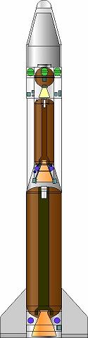
The RSA-4 ICBM / satellite launcher was a planned follow-on to the RSA-3. A large new first stage optimised the vehicle and more than doubled the payload in comparison to the RSA-3. It is not known if the project reached the point of testing of the large motor, which was equivalent to the US Peacekeeper first stage.
The second and third stages were essentially those of the RSA-3. The fourth stage was clearly adapted from an ICBM MIRV post-boost bus platform. As an ICBM or orbital nuclear system the RSA-4 would have been capable of delivering a single 700 kg warhead anywhere on earth.
Work on the RSA-4 was cancelled in 1994. An attempt was made by Houwteq to market the RSA-4 as a launcher for MEO earth satellite constellations. It was not to be...but the sales brochure from that effort survives and is reproduced below.
Houwteq
FOREWARD
The South African Space Industry is spearheaded by Houwteq. Houwteq is the prime contractor in the space industry for space systems and services and is supported by twenty local subcontractors. Most of the subcontractors had established proven capabilities in the high technology field before joining the space industry. Houwteq is the systems house responsible for the space system design, assembly, integration, launch preparation and execution and project management of space activities. The company is located near Grabouw in the Cape Province. Houwteq's subcontractors are responsible for the design, development,, qualification, production, as well as technical and logistic support, at configuration item level.
Houwteq is offering a comprehensive launch service with its RSA-4 Launch Vehicle from the Overberg Test Range situated in South Africa.
Chapter 1
1.1 Purpose of Document
This document is intended as an introduction to the RSA-4 launch vehicle and the launch service offered to prospective clients for placing small to medium sized payloads into low earth orbit (LEO).
The document covers the following aspects;
Houwteq offers a comprehensive service for LEO launches including the launch vehicle, the launch facility and associated services.
The RSA-4 launch vehicle comprises three solid propellant boost stages and a hydrazine powered fourth stage for accurate orbit injection and positioning, It can lift a satellite with a mass of 550 kg into a circular orbit at a height of 1400 km and a inclination of 55 degrees.
Provision is made for a payload volume of 10.4 m3 with a maximum diameter of 2.2 m.
II is possible to launch two satellites into different orbits which are in the same orbital plane. The launch vehicle is described in more detail in Chapter 2.
Launches are conducted from the newly established facility at the Overberg Test Range at the southernmost tip of Africa on the south-eastern coast of the western Cape at Lat 34 deg 35 min S and Long 20 deg 19 min E. The facility (OTR), which extends over a total area of 43,000 hectares, is situated close to the villages of Waenhuiskrans and Bredasdorp. Cape Town, one of the major cities in South Africa, is located approximately 200 km from OTR and has a commercial airport capable of handling large airliners. A good quality highway exists between Cape Town and OTR.
A modern air base adjacent to OTR can accommodate all types of aircraft, The use of this facility could be negotiated for specific transport arrangement if required.
Chapter 2
2.1 System Description
Figure 2.1 shows the overall dimensions and layout of the RSA-4 launch vehicle. It comprises four stages. The first three have solid propellant motors to lift the satellite into orbit. Orbit raising is then performed by means of the fourth hydrazine-propelled stage, which is also used to make fine orbital adjustments to place the satellite accurately into the required orbit. The masses for the stages are respectively 66 tonne for the first stage, 10 tonne for the second, 3 tonne for the third, and approximately 300 kg for the final stage, which gives an all-up mass of 80 tonne for the complete system. The overall length is 23.5 m with a diameter of 2.4 m.
 | Title Page - Introduction to the RSA-4 Launch Vehicle Credit: Denel / Houwteq. 18,267 bytes. 346 x 455 pixels. |
2.2 First Stage
The first stage (Figure 2.2) is propelled by means of a solid propellant motor weighing 62.6 tonne, of which 58 tonne is propellant. It delivers an impulse of 139,000 kNs at sea level and burns for 73 s with an average thrust of just under 200 tonne. The expansion ratio of the carbon-phenolic expansion cone is 14. A graphite throat insert is used. The composite casing is made of Kevlar and covered with cork for thermal insulation. The base and the interstage structures are made of aluminium 2219. Control is done by means of LITVC, as well as air vanes manufactured from honeycomb material. Also situated at the base is a PCM unit for telemetry acquisition and an S-band telemetry transmitter. Power is supplied by 28 volt silver-zinc triggered batteries. In the interstage section on top of the motor is the pyrotechnic activation unit for motor ignition, separation from the launch platform, and detonation of the cutting cords for motor destruction.
 | Figure 2.1 - RSA-4 Launch Vehicle Credit: Denel / Houwteq. 19,328 bytes. 645 x 875 pixels. |
Stage 2 (Figure 2.3) is very similar to stage 1 with following differences:
The motor with 9 tonne solid propellant burns for 52 s and delivers an impulse of 24,500 kNs with an average thrust of 40 tonne. Control is done by injecting strontium perchlorate into the motor flame. It is stored in a torus around the nozzle throat and pressurized by means of helium.
The second stage also houses the receivers for destruct in case of malfunction. The destruct channels are redundant and destruct is initiated on receipt of a destruct signal or in case of loss of the carrier wave.
 | Figure 2.2 - Stage 1 Credit: Denel / Houwteq. 6,617 bytes. 640 x 324 pixels. |
2.4 Third Stage
Stage 3 (Figure 2.4) houses the autopilot for digital implementation of the guidance and control algorithms, onboard safety implementation, initiation of discrete events like stage separation, and power switching. Communication is via a 1553 bus. Navigation is performed by a strapdown platform and GPS.
Power is supplied from 28V triggered batteries. Also housed in the third stage is the equipment for tracking and monitoring the launch vehicle, i.e. telemetry, television for monitoring stage separation, a Doppler beacon for measuring velocity and a radar transponder for measuring velocity and range. The structure is made of aluminium. The third stage motor weighs 2 tonne, with 1,9 tonne solid propellant in a titanium casing and a nozzle with an expansion ratio of 60. It burns for 92s and delivers a specific impulse of 292 s.
 | Figure 2.3 - Stage 2 Credit: Denel / Houwteq. 5,241 bytes. 530 x 219 pixels. |
The purpose of the fourth stage (Figure 2.5) is to raise the orbit and to make small orbital adjustments. For this purpose it is equipped with a reactive control system comprising four 50 liter hydrazine tanks, filled to the right level for the particular mission and pressurized by helium, and ten thrusters. Four 200 N thrusters are used for roll control, four 25 N thrusters for pitch and yaw control and two 200 N thrusters for orbit raising. Figure 2.5 shows the layout of the reactive control system.
Navigation is done by means of GPS with a CA code receiver. Rate gyros and accelerometers measure the orientation and velocity increments needed by the control computer for control loop implementation.
 | Figure 2.4 - Stages 3, 4 and Payload Credit: Denel / Houwteq. 5,812 bytes. 270 x 392 pixels. |
The fairing which protects the satellite is made of a honeycomb composite material and is jettisoned sideways in two halves after stage 2 burn-out.
 | Figure 2.5 - Stage 4 with Third Stage Motor Credit: Denel / Houwteq. 16,002 bytes. 408 x 482 pixels. |
Chapter 3
3.1 Introduction
The RSA-4 launch vehicle is used to lift small to medium sized satellites into elliptical or circular low earth orbits at inclinations between 37 deg and 90 deg and in sun synchronous. Two satellites can be launched simultaneously, if necessary into different orbits, which must however be in the same orbital plane. Since many different missions are possible, the performance figures and flight profiles are presented for selected cases.
3.2 Lifting Capability
The payload mass which can be placed into a circular orbit for different orbital orbits is given in Figure 3.1 for 55 deg and 90 deg inclinations.
 | Figure 3.1 - RSA 4 Satellite Mass in Circular Orbit Credit: Denel / Houwteq. 15,833 bytes. 603 x 493 pixels. |
3.3 Injection Accuracy
The 2-sigma values for the accuracy of injection into a circular orbit are as follows:
 | Figure 3.2 - RSA 4 Acceleration During Launch Credit: Denel / Houwteq. 12,710 bytes. 594 x 486 pixels. |
As an example of typical values for the main trajectory parameters, their time variation is presented in Figures 3.2 to 3.6 for a 550 kg spacecraft launched at a 55 deg inclination.
3.5 Spacecraft Deployment
In the standard mode the spacecraft will be spun up to >1 rev/s and will be separated with a relative velocity > 0.5 m/s with an angle between the spacecraft longitudinal axis and the velocity vector <5 deg. Requests for other deployment conditions will be handled on an individual basis.
3.6 Launch Sequence
 | Figure 3.3 - RSA 4 Velocity During Launch Credit: Denel / Houwteq. 11,241 bytes. 608 x 493 pixels. |
As an example the flight parameters and sequence of events are presented for the injection of two satellites into a 1400 km circular orbit.
During the first few seconds after ignition the launcher is rotated from the vertical and flies a gravity turn during the first powered stage. At a height of 40 km, 55 km downrange, the first stage separates, the sleeve is jettisoned, and the second stage motor is ignited. It burns out at a height of 97 km, 230 km downrange, and is jettisoned 25 s later.
 | Figure 3.4 - RSA 4 Ground Range During Launch Credit: Denel / Houwteq. 9,324 bytes. 597 x 470 pixels. |
 | Figure 3.5 - RSA 4 Launch Trajetory Credit: Denel / Houwteq. 10,796 bytes. 597 x 470 pixels. |
 | Figure 3.6 - Dynamic Pressure During Launch Credit: Denel / Houwteq. 13,837 bytes. 572 x 457 pixels. |
It will be possible to inject the two spacecraft into different elliptical or circular orbits provided that they are in the same orbital plane and that the energy requirements are within bounds. Provision is made to give a payload of 550 kg a velocity increment of 300 m/s with the fourth stage.
 | Figure 3.7 - Launch Sequence Credit: Denel / Houwteq. 7,802 bytes. 632 x 447 pixels. |
If the spacecraft is to be launched into an orbit with a specified nodal angle and if the direction of motion in the orbit is prescribed, then energy considerations and the range safety volume restrict the opportunity for launching to a window of fifteen minutes around a particular time once a day.
It will be possible to monitor the launch from the Overberg ground station up to burnout of the third stage motor. This is the most intensive part of the launch. Separation of the third stage motor and the velocity correction directly afterwards take place after it has disappeared over the horizon During development flight test these events will be monitored from a downrange telemetry station onboard a ship.
 | Figure 3.8 - Stage 4 / Satellite Separation in 1400 km Orbit Credit: Denel / Houwteq. 10,807 bytes. 546 x 475 pixels. |
Figures 3.9 and 3.10 show the ground track of the satellite for a 55 deg inclination. At an orbital height of 1400 km it will pass within view of the Overberg ground station for the first six revolution.
 | Figure 3.9 - Satellite Ground Track for 65 deg Inclination Credit: Denel / Houwteq. 33,282 bytes. 675 x 411 pixels. |
LEO Payload: 770 kg. to: 400 km Orbit. at: 55.0 degrees. Payload: 550 kg. to a: 1400 km, 55 degree circular orbital trajectory. Liftoff Thrust: 200,000 kgf. Total Mass: 80,000 kg. Core Diameter: 2.4 m. Total Length: 23.5 m.
 | Figure 3.10 - Satellite Ground Track from Polar Perspective for 55 deg Inclination Credit: Denel / Houwteq. 15,409 bytes. 582 x 485 pixels. |
 | Figure 3.11 - Ground Station Coverage for Delta-V Burn to Circularize Orbit at 1400 km Credit: Denel / Houwteq. 12,255 bytes. 536 x 442 pixels. |
The RSA-3 satellite launcher began development as an IRBM in the 1980's. It was developed with the assistance of Israel. The satellite launcher was found not to be viable commercially and so was cancelled in mid-1994. The Overberg Test Range near Bredasdorp, 200 km east of Cape Town, was used for test flights.
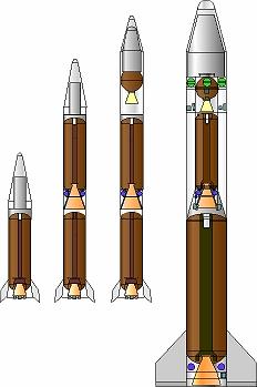 | RSA-1 , -2, -3, -4 12,494 bytes. 232 x 349 pixels. |
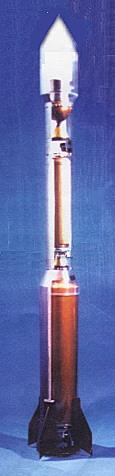 | Model of RSA-4 - Model of RSA-4 space launcher, the planned follow-on to the RSA-3. The RSA-4 would have been 23.5 m long and could lift 550 kg into a 1,400-km orbit. This model differs in some details from drawings in the RSA-4 sales brochure. 9,402 bytes. 115 x 476 pixels. |