Credit: US Army. 27,665 bytes. 198 x 413 pixels.
| astronautix.com | Project Horizon - Chapter 2 |
|
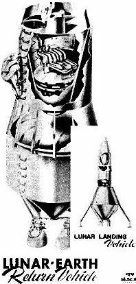
| Horizon LERV - Lunar-Earth Return Vehicle as designed by Von Braun team for Project Horizon Credit: US Army. 27,665 bytes. 198 x 413 pixels. |
PROJECT HORIZON REPORT
A U. S. ARMY STUDY FOR THE ESTABLISHMENT
OF
A LUNAR OUTPOST
A. OBJECTIVES AND SCOPE OF THE STUDY
This part of the study presents applicable technical information which substantiates the feasibility of the expedited establishment of a lunar outpost, and it relates U. S. capabilities and developments to the accomplishment of the task It is comprehensive in its scope, covering the design criteria and requirements for all major elements of the program including the lunar outpost, the earth-lunar transportation system, the necessary communications systems and the considerable earth support facilities and their operation. The technical assumptions concerning design parameters for this program are realistic yet conservative. Likewise, the assumptions which concern the scope and magnitude of other U. S. programmes which will support HORIZON are reasonable and in line with current and projected programs.
B. RESUME OF THE TECHNICAL PROGRAM
The basic carrier vehicles for Project HORIZON will be the SATURN I and II. The SATURN I, currently being developed under an ARPA order, will be fully operational by October 1963. The SATURN II, which is an outgrowth of the SATURN I program, could be developed during the period 1962-1964. The SATURN II will utilise improved engines in the booster and oxygen/hydrogen engines in all of its upper stages.
By the end of 1964, a total of 72 SATURN vehicles should have been launched in U. S. programmes, of which 40 are expected to contribute to the accomplishment of HORIZON. Cargo delivery to the moon begins in January 1965. The first manned landing by two men will be made in April 1965. The build-up and construction phase will be continued without interruption until the outpost is ready for beneficial occupancy and is manned by a task force of 12 men in November 1966.
This build-up program requires 61 SATURN I and 88 SATURN II launchings through November 1966, the average launching rate being 5. 3 per month. During this period some 490,000 pounds of useful cargo will be transported to the moon
During the first operational year of the lunar outpost, December 1966 through 1967, a total of 64 launchings have been scheduled These will result in an additional 266,000 pounds of useful cargo on the moon
The total cost of the eight and one-half year program presented in this study is estimated to be six billion dollars. This is an average of approximately $700 million per year. These figured are a valid appraisal, and, while preliminary, they represent the best estimates of experienced, non-commercial, agencies of the government. Substantial funding is undeniably required for the establishment of a U. S. lunar outpost; however, the implications of the future importance of such an operation should be compared to the fact that the average annual funding required for Project HORIZON would be less than two percent of the current annual defence budget.
C. OUTPOST
The lunar outpost proposed for Project HORIZON is a permanent facility capable of supporting a complement of 12 men engaged in a continuing operation The design of the outpost installation herein is based on realistic requirements and capabilities, and is not an attempt to project so far into the future as to lose reality. The result has been a functional and reliable approach upon which men can stake their lives with confidence of survival.
 | Horizon Final Base - Project Horizon Lunar Outpost in as it would appear by late 1965 Credit: US Army. 10,141 bytes. 463 x 327 pixels. |
The exact location of the outpost site cannot be determined until an exploratory probe and mapping program has been completed. However, for a number of technical reasons, such as temperature and rocket vehicle energy requirements, the area bounded by +-20 deg latitude/longitude of the optical centre of the moon seems favourable. Within this area, three particular sites have been chosen which appear to meet the more detailed requirements of landing space, surface conditions, communications, and proximity to varied lunar "terrain".
A rather extensive lunar mapping program is already underway in order to satisfy existing requirements in Astro-Geodesy. Maps to a scale of 1:5,000,000 and 1:1,000,000 are planned for completion by December 1960 and August 1962, respectively. Larger scale mapping will then be undertaken for several specific site selections.
 | Horizon Compartment - Cross Section of Typical Project Horizon Lunar Outpost Compartment Credit: US Army. 3,152 bytes. 423 x 215 pixels. |
The design of the lunar outpost facilities will, of course, be dominated by the influence of two factors - the lunar environment and the space transportation system capabilities. A few of the more pronounced primary lunar environmental parameters are listed below:
These and many other unfamiliar environmental conditions require that every single item which is to be placed on the lunar surface have a design which is compatible with these phenomena. However, a careful determination has been made of man's requirements to live in this environment, and it appears that there is no area which cannot be adequately solved within the readily available state-of-the-art.
 | Horizon Camp - Overall View of Initial Project Horizon Lunar Construction Camp Credit: US Army. 8,021 bytes. 546 x 363 pixels. |
The first two men will arrive on the lunar surface in April 1965. They will be guided to an area in which the cargo build-up for future construction has already begun. Their landing vehicle will have an immediate return-to-earth capability; however, it is intended that they remain in the area until after the arrival of the advance party of the construction crew. During their stay, they will live in the cabin of their lunar vehicle which will be provided with necessary life essentials and power supplies. For an extended stay, these will be augmented by support from cargo previously and subsequently delivered to the site by other vehicles.
The mission of the original two men will be primarily one of verification of previous unmanned environmental investigations and confirmation of the site selection and cargo delivery.
 | Horizon First Camp - Layout of Project Horizon Lunar Basic 12-Man Outpost Credit: US Army. 6,839 bytes. 536 x 363 pixels. |
During the construction period, this force will be gradually augmented until a final complement of 12 men is reached. The construction camp is a minimum facility and will be made operational within 15 days after the beginning of active work at the outpost site. Two nuclear reactors are located in holes as shown in the left portion of Fig. I-1. These provide power for the operation of the preliminary quarters and for the equipment used in the construction of the permanent facility. The main quarters and supporting facilities are shown being assembled in the open excavation to the right-centre of the figure. These cylinders will also ultimately be covered with lunar material. Empty cargo and propellant containers have been assembled and are being used for storage of bulk supplies, weapons, and life essentials such as insulated oxygen/nitrogen tanks. Two typical surface vehicles are shown: one is a construction vehicle for lifting, digging, scraping, etc.; the other is a transport vehicle for more extended distance trips needed for hauling, reconnaissance, rescue, and the like. In the left background, a lunar landing vehicle is settling on the surface. A lightweight parabolic antenna has been erected near the main quarters to provide communications with earth.
 | Horizon Space Suit - Project Horizon Typical Lunar Suit Credit: US Army. 5,245 bytes. 440 x 345 pixels. |
A number of factors influenced the decision to locate the main structures beneath the surface. Among these were the uniform temperature available (approximately -40 deg F), protection from meteoroids, security, good insulating properties of the lunar material, and radiation protection. Each of the quarters and cylinders will be a special double-walled "thermos bottle type" vacuum tank with a special insulating material in the space between the walls. (Vacuum is usually maintained simply by venting the tank to the lunar void. ) Despite the ambient subsurface temperature of -40 deg F, the heat losses from these special tanks will be remarkably low. Investigations show that the incidental heat given off by an adequate internal lighting system will nominally supply essentially all of the heat required to maintain comfortable "room" temperature in the outpost quarters.
 | Horizon Transport - Project Horizon Earth-Moon Transporation Schemes Credit: US Army. 4,046 bytes. 495 x 378 pixels. |
4. Personnel Equipment
For sustained operation on the lunar surface a body conformation suit having a substantial outer metal surface is considered a necessity for several reasons: (1) uncertainty that fabrics and elastomers can sustain sufficient pressure differential without unacceptable leakage; (2) meteoroid protection; (3) provides a highly reflective surface; (4) durability against abrasive lunar surface; (5) cleansing and sterilisation. Figure I-5 shows a cutaway and "buttoned up" concept for such a suit. It should be borne in mind that while movement and dexterity are severe problems in suit design, the earth weight of the suit can be allowed to be relatively substantial. For example, if a man and his lunar suit weigh 300 pounds on earth, they will only weigh 50 pounds on the moon
 | Horizon Initial Plan - Project Horizon Initial Two Man Round Trip to Lunar Surface Credit: US Army. 8,064 bytes. 507 x 377 pixels. |
5. Environmental Research
In order to corroborate essential environmental data, a series of unmanned experiments are planned. There are early data requirements in the areas of radiation, meteoroid impacts, temperatures, magnetic field, surface conditions, ionisation, radio propagation and biological effects.
D. SPACE TRANSPORTATION SYSTEM
1. Flight Mechanics
 | Saturn I (1959) - Saturn I configuration for Project Horizon Credit: US Army. 2,658 bytes. 107 x 473 pixels. |
 | Saturn I Stages - Saturn I , stages 1 to 3, configuration for Project Horizon (1959) Credit: US Army. 5,632 bytes. 335 x 419 pixels. |
The first scheme (1 above) is the direct approach, that is, a vehicle would depart the earth's surface and proceed directly to the lunar surface using a retro-rocket or landing stage for the final landing manoeuvre. Since the moon has no appreciable atmosphere, a rocket type propulsion system will be required for the landing. The second scheme (2 and 3 above) shown is that for proceeding first into an earth orbit and later departing the orbit for the flight to the lunar surface, again using a landing stage. In either scheme, the flight time from the earth or earth orbit to the moon will be the same.
The direct scheme, which is the most straightforward, has two advantages: first, it offered the shortest flight time from the earth's surface to the lunar surface since an orbital stopover is not required.
 | Saturn II (1959) - Saturn II configuration for Project Horizon Credit: US Army. 2,913 bytes. 152 x 496 pixels. |
To illustrate this point, it has been assumed in the study that the. first men arriving on the moon will be provided with an immediate return capability. Figure I-7 depicts the vehicular requirements for the two schemes.
The direct approach would require a six stage vehicle with a lift-off thrust of 12 million pounds, as compared to a two-million-pound thrust vehicle for the orbital schemes. By placing the upper stage and payload of two-million-pound thrust vehicle into orbit, and with additional vehicles as shown, performing a fuel transfer and checkout operation, the same mission, that of transporting two men to the moon and returning them to earth, could be accomplished.
 | Saturn II Stages - Saturn II, Stages 1 through 4, configuration for Project Horizon (1959) Credit: US Army. 6,097 bytes. 424 x 358 pixels. |
For the return to earth, from either the earth orbit or the lunar surface, aerodynamic braking will be used, since it allows significant overall payload increases when compared to rocket braking. The aerodynamic braking body used for this study is similar in shape to a JUPITER missile nose cone modified by the addition of movable drag vanes at the base of the cone. Though the size varies, the same basic shape was considered for use from the lunar surface to earth act as for use from the 96-minute orbit to the earth's surface. Studies show that, within acceptable limits of entry angle, the vehicle can make a successful descent which is well within the physical tolerances imposed by man's presence, and which can be guided with acceptable accuracy for final recovery. The recent successful flight and subsequent recovery of two primates aboard a nose cone further substantiates the validity of this approach to earth return braking. This test vehicle was fired to IRBM range and, due to the steep re-entry angle, the decelerative forces r� associated with this operation were many times greater than expected for project HORIZON trajectories.
 | Horizon Space Dock - Assembly and fuelling of translunar stages and spacecraft for Project Horizon in Equatorial Earth Orbit Credit: US Army. 7,917 bytes. 448 x 312 pixels. |
Only two basic carrier vehicles are required to carry out Project HORIZON - SATURN I and a further development, SATURN II.
The SATURN I vehicle, shown in Figs. I-8 and I-9 consists of a clustered booster with a lift-off thrust of 1,504, 000 pounds, a twin engine second stage of about 360,000 pounds of thrust, and a lox / hydrogen (O2/H2) third stage of 30,000 pounds of thrust. The initial performance of this vehicle will enable it to place 30,000 pounds of net payload in a 96-minute orbit and 7,500 pounds of net payload to earth escape velocity. It will be powered by eight North American H-l engines which are a greatly simplified version of the engine used in JUPITER, THOR, and ATLAS. The second stage is a modified version of the TITAN booster. The third stage is a modified CENTAUR vehicle currently under development by Pratt & Whitney and Convair.
 | Horizon LLV - Project Horizon Lunar Landing Vehicle Credit: US Army. 5,403 bytes. 295 x 501 pixels. |
 | Horizon ORV - Project Horizon Orbital Return Vehicle Credit: US Army. 5,566 bytes. 264 x 457 pixels. |
Figure I-12 is a conceptual view of the operations in the equatorial earth orbit. The operation in orbit is principally one of propellant transfer and is not as assembly job. The vehicle being fuelled is the third stage of a SATURN II with a lunar landing and return vehicle attached. The third stage of the SATURN II was used in bringing the combination into orbit and has thus expended its propellants. This stage is fuelled in orbit by a crew of approximately ten men after which the vehicle then proceeds on to the moon. It is planned to send all personnel and approximately 1/3 of the cargo to the moon by the orbital method.
 | Horizon Manpower - Project Horizon Personnel Space Transportation Requirements Credit: US Army. 6,413 bytes. 563 x 351 pixels. |
 | Horizon Project Plan - Project Horizon Vehicle Requirements and Launching Schedule Credit: US Army. 9,459 bytes. 698 x 355 pixels. |
To sustain the orbital station crew and to provide for their safe return to earth, an orbital return vehicle such as shown in Fig. I-14 will be provided. This vehicle may be used in conjunction with another established United States orbital station, or it may be used as a basis for a minimum orbital station needed to support Project HORIZON. It is capable of carrying from 10 to 16 men. It will be carried into orbit by a SATURN I during the first part of the program and replaced by a SATURN II in 1967.
 | Horizon Comm Links - Project Horizon Earth Complex and Lunar Communication Links Credit: US Army. 3,378 bytes. 350 x 248 pixels. |
An investigation of the guidance problems concerned with Project HORIZON indicates that the necessary accuracies and reliabilities can be met by adaptations, combination and slight extensions of known and available guidance hardware and techniques. Final injection velocity, which marks the beginning of the coast phase of the trajectory to the moon, will be controlled by conventional means. Mid-course guidance will assure that the lunar landing vehicle would come within approximately 20 km (11 nautical miles) of the selected point. The terminal guidance system, which would be target oriented, would reduce the three standard deviation error at landing to approximately 1.5 km.
E. TRANSPORTATION SYSTEM INTEGRATION
The development and integration of the space carriers to support HORIZON have been carefully outlined and various considerations as to compatibility, size, development schedule, and overall mission have been included and discussed in detail in Volume II.
 | Horizon Lunar Comms - Project Horizon Typical Tracking and Lunar Communication Site Credit: US Army. 3,570 bytes. 424 x 202 pixels. |
 | Horizon Lunar Net - Project Horizon Lunar Communication Net Credit: US Army. 4,323 bytes. 413 x 312 pixels. |
The communications required for Project HORIZON are logically divided into an earth-based and lunar-based complex. Each of these complexes may be considered as having two functions - communications and surveillance. Of particular significance for the earth-based complex is the 24-hour communications satellite system presently under development; As illustrated in Fig. I-17 such a system will provide the capability of constant communications with both space vehicles in transit and the lunar outpost.
In addition to the 24-hour communications satellite system, the current development program of a world-wide surveillance net will provide space surveillance for the United States during the 1960 era. The basic hardware and techniques used in this net are directly applicable to HORIZON. Figure I-18 illustrates schematically how such a world net station could be expanded to support HORIZON by the addition of two additional 85-foot antennas and other equipment.
 | Horizon Launch Site - Project Horizon Terrestrial Launch Site Credit: US Army. 11,129 bytes. 434 x 310 pixels. |
In addition to voice communication between members of the lunar party, a number of other electronic devices will be used at the outpost, These include TV receipt and transmission, transmission of still photographs, homing and location devices, instantaneous self-contained emergency communications packs (for distress signals to earth), infrared detectors, and radar detectors.
 | Horizon R&D - Project Horizon Organization for Research and Development Credit: US Army. 8,471 bytes. 585 x 377 pixels. |
A survey was made to determine the adequacy of the Atlantic Missile Range and Pacific Missile Range for the accomplishment of Project HORIZON. The results of this survey indicated that, all things being considered, neither site was suitable. Since a new launch site will be required, a study was made to determine the optimum location and requirements for such a site.
The results of this study are discussed in detail in Volume II and illustrated in Fig. I-20. A total of eight launch pads are required. This facility will support the requirements of HORIZON and would also provide additional capacity for other United States programmes.
The equatorial location of the new launch site would provide very real advantages in terms of payload capability, guidance simplicity, and operational launching schedules in terms of increased latitude of appropriate firing times. Two sites stand out when compared to others: Brazil and Christmas Island. Both of these locations appear feasible; however, more detailed criteria will have to be established to make the best choice. Cost and early availability may ultimately be the governing factors. It is emphasised that site acquisition and initiation of launch site construction is one of the most critical items in the program with respect to lead-time. For the purposes of this study it has been assumed that the Brazil site would be used.
 | Horizon Main Base - Project Horizon Cross Section Through Main Facility Credit: US Army. 5,447 bytes. 534 x 256 pixels. |
The logistic support for Project HORIZON has been studied in overall scope as well as detailed investigations of specific areas such as manufacturing considerations, transportation considerations, personnel, and personnel training.
The results of the studies show very clearly that military participation in the logistic portion for Project HORIZON is not only desirable, but mandatory. No attempt has been made to determine the level of military participation since such items as the world-wide political situation will play an important part in the ultimate decision.
I. RESEARCH AND DEVELOPMENT
Project HORIZON has been divided into six phases which include R&D as well as the operational aspects of the overall program. The schedule for each phase is illustrated on Fig. I-21 and discussed below:
 | Horizon Simulator - Project Horizon View of Flight Simulator - a combined high-G and zero-G sled running down the side of a cliff! Credit: US Army. 7,222 bytes. 297 x 390 pixels. |
Phase II - The detailed development and funding plan will require a more detailed study with limited experimentation. This phase will require approximately eight months to complete and will cost $ 5.4 million.
Phase III - The hardware development and system integration phase constitutes the majority of the development effort. In Phase III all:
required to accomplish the project objectives will be developed.
Phase IV - The construction of the lunar outpost involves the utilisation of the systems and procedures developed in Phase III and is in actuality an operational phase of the program. The completion of this phase will accomplish the initial objective of the program: "establish a manned lunar outpost. "
Phase V - The initial period of outpost operation will begin in December 1966 and will constitute the first completely operational phase of the program.
Phase VI- The expansion of initial outpost operational capabilities could begin at any time after December 1966. For the purpose of this study it has been assumed to begin in January 1968.
1. Basic and Supporting Research
The importance of a strong basic and supporting research effort in support of a project of this nature cannot be overstated. Typical areas requiring attention are food and oxygen, clothing, chemical, biological, radiological bio-medical, vacuum conditions, weightlessness, meteoroids, lunar-based systems, moon mapping, explosives in lunar environment, power generation, material and lubricants, liquid hydrogen production and handling, and lunar "soil" mechanics.
2. Project HORIZON Development Program
As mentioned above, a strong basic and supporting research program will be required to accomplish the HORIZON development program, and ultimately the project objectives. The development program for this project is basically covered by the first three phases of the project outlined above, the first of which has been completed. Phase II, the next step in the development program, must be accomplished in the time scale indicated in Fig. I-21 if the United States is to succeed in establishing the first lunar outpost. The development plan, generated in Phase II will spell out in considerable detail the developments required in Phase III, as well as requirements for later phases.
Basically, Phase III will be the development portion of the project. During this phase, al1 development required to accomplish the project objectives will be satisfied.
3. Research and Development Facilities
Several unique facilities will be required to support HORIZON. Figure I-22 is a view of a large lunar environmental simulator which will provide a capability for research, development, testing and training for HORIZON as well as other projects in the national space program. Figure 1-23 illustrates a space flight simulator which will provide for research and training of effects associated with boost acceleration, coasting, weightlessness, and braking deceleration. In addition, medical research facility is located in conjunction with this site.
Continued - - go to Chapter 3.